Digital Image Correlation

Digital Image Correlation: Mapping Deformations with Precision

Digital Image Correlation is a non-contact optical technique that measures deformation, displacement, and strain on material surfaces. By comparing digital images taken before and after deformation, it provides precise, full-field data, essential for material testing, structural analysis, and engineering research.

Overview

Digital Image Correlation (DIC) is a powerful and versatile technique used in the field of experimental mechanics and materials science to analyze and quantify deformations and displacements in a wide range of structures and materials. This non-contact optical method has gained popularity due to its ability to provide high-resolution measurements for both static and dynamic loading conditions. In this comprehensive guide by Academic Block, we will explore the principles, applications, challenges, and advancements in Digital Image Correlation.

1. Introduction to Digital Image Correlation

Digital Image Correlation is a full-field measurement technique that allows for the precise tracking of surface deformations, both in 2D and 3D, by analyzing images of the object under investigation. It is a non-destructive and non-contact method, making it suitable for various applications in industries such as aerospace, automotive, defense, civil engineering, mechanical, medical and biomechanics.

The development of Digital Image Correlation (DIC) is attributed to Prof. Sutton, Prof. Wolters, Prof.. Peters, Prof. Ranson, and Prof. McNeill. The development of DIC can be traced back to the 1980s when these researchers began exploring non-contact optical methods for measuring displacements and strains on the surfaces of objects undergoing deformation.

Prof. M. A. Sutton is often referred to as the “fathers of Digital Image Correlation” for his pioneering and continous work since 1980s. Prof. Sutton, along with his colleagues and students, significantly contributed to the establishment and advancement of DIC as a powerful and widely used technique for measuring full-field displacements and strains in materials and structures. Their early work laid the foundation for the principles and methodologies that are now integral to Digital Image Correlation.

1A. Principles of Digital Image Correlation

DIC relies on the comparison of images captured before and after deformation to determine the displacement and strain fields. The basic steps involved in DIC include image acquisition, image preprocessing, pattern matching, and post-processing. The technique is based on the assumption that the intensity patterns on the surface of the object are unique and can be tracked accurately throughout the deformation process.

1B. Image Acquisition

High-quality images are essential for accurate DIC results. The selection of the imaging system, lighting conditions, and camera settings plays a crucial role in the success of the DIC analysis. Generally, high-resolution cameras with adequate frame rates are employed to capture the deformation process.

1C. Image Preprocessing

To enhance the accuracy of DIC, image preprocessing is performed. This includes tasks such as image cropping, filtering, and normalization to remove noise and improve the contrast of the images. Proper preprocessing ensures that the DIC algorithm can accurately identify and track the surface speckle pattern.

1D. Pattern Matching

Pattern matching is the core of DIC, where the software identifies and tracks unique points or patterns on the surface of the object. This process involves comparing the reference and deformed images and finding the displacement vectors for each point. Various algorithms, such as correlation-based methods, are employed for speckle pattern matching.

1E. Post-Processing

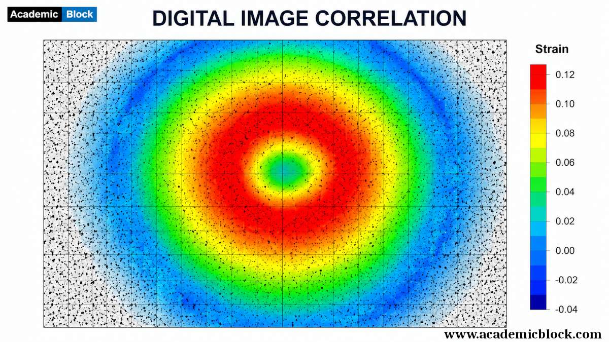
Achieving subpixel accuracy in displacement measurements is crucial for the precision of DIC. Various interpolation and optimization techniques are employed to enhance the accuracy of the calculated displacements. Once the displacement and strain fields are obtained, post-processing is carried out to analyze and visualize the results. This may involve contour plots, displacement maps, and strain distribution maps, providing valuable insights into the material behavior and structural response.

2. Applications of Digital Image Correlation

DIC has found applications in a wide range of fields due to its versatility and accuracy. Some key areas where DIC is extensively used include:

2.1 Material Characterization

DIC finds extensive use in material testing and characterization, enabling researchers to obtain accurate and high-resolution strain maps. This is particularly valuable in understanding the mechanical properties of materials under various loading conditions like projectile impact, and blast induced shock, aiding in the development of advanced materials for specific applications.

2.2 Structural Health Monitoring

In the realm of structural engineering, DIC serves as a powerful tool for structural health monitoring. By analyzing deformations and strains in real-time, engineers can assess the structural integrity of bridges, buildings, and other critical infrastructure components, ensuring early detection of potential issues and enhancing safety.

2.3 Biology

DIC has made significant inroads into the field of biomechanics, allowing researchers to study the deformation of biological tissues and organs. This has implications in medical research, sports science, and orthopedics, offering insights into the mechanics of bones, muscles, and soft tissues.

2.4 Aerospace and Automotive Industries

In industries where materials undergo complex loading conditions, such as aerospace and automotive, DIC plays a crucial role in understanding the behavior of components subjected to varying forces. This information is vital for optimizing designs, improving fuel efficiency, and ensuring the safety of critical components.

3. Advancements in Digital Image Correlation

The field of DIC has seen continuous advancements, driven by the need for higher accuracy, faster processing, and improved ease of use. Some notable developments include:

3.1 3D Digital Image Correlation

Traditional DIC is a 2D technique, providing surface strain information in two dimensions. However, 3D DIC has emerged to capture the full three-dimensional deformation of objects. This is achieved by using multiple cameras or stereo imaging systems.

3.2 High-Speed Digital Image Correlation

High-speed DIC has become crucial for applications involving dynamic events, such as bullet impact, car crash, blasts, and vibration analysis. Advancements in camera technology and image processing algorithms have enabled DIC to be applied in real-time or near real-time scenarios.

3.3 Infrared Digital Image Correlation

Infrared DIC extends the capabilities of traditional DIC by allowing measurements in environments with low visibility or where conventional lighting methods are impractical. This is particularly beneficial in applications such as thermal deformation analysis.

3.4 Machine Learning Integration

The integration of machine learning techniques with DIC has shown promise in enhancing speckle pattern recognition, reducing computational time, and improving the robustness of DIC algorithms. Neural networks and deep learning approaches are being explored to automate the identification and tracking of deformation patterns.

3.5 DIC Coupled with Other Techniques

Researchers are increasingly combining DIC with other measurement techniques, such as infrared thermography and acoustic emission, to gain a more comprehensive understanding of material behavior. This multi-modal approach enhances the accuracy and depth of information obtained from experiments.

4. Mathematics behind the 2D Digital Image Correlation

Digital Image Correlation (DIC) involves several mathematical equations and algorithms to analyze images, track displacements, and compute strain fields. Below are the key mathematical concepts and equations behind Digital Image Correlation:

4.1 Image Correlation:

The fundamental concept of DIC is based on correlating pixel intensities between the reference and deformed images. One of the most common correlation measures is the normalized cross-correlation function (NCC). The NCC between two images A and B is given by:

NCC(x,y) = Num/Den; where

Num = ∑i,j(A(i,j)−A’)(B(i+x,j+y)−B’);

Den = sqrt(∑i,j(A(i,j)−A’)2i,j(B(i+x,j+y)−B’)2);

where A’ and B’ are the means of images A and B, and (x, y) are the displacement coordinates.

4.2 Displacement Interpolation:

Once the correlation peaks are found, subpixel accuracy is achieved by fitting a mathematical function to the correlation surface. Bicubic or quadratic interpolation is commonly used. The displacement field (u,v) at each pixel is obtained through interpolation.

4.3 Transformation Equations:

To obtain the displacement field, transformation equations are applied to relate the displacements at discrete points to the overall deformation. In 2D DIC, the transformation equations can be expressed as:

x′=x+u; y′=y+v;

where (x, y) are the coordinates in the reference image, and (x’, y’) are the coordinates in the deformed image.

4.4 Strain Calculation:

Strain is calculated based on the displacement field. For small strains, the engineering strain εε can be approximated by the spatial derivatives of displacement:

εx=∂u/∂x

εy=∂v/∂y

γxy= 0.5 (∂u/∂y+∂v/∂x)

4.5 Finite Deformation:

For cases involving large deformations, the Green-Lagrangian strain tensor is commonly used:

Exx = (∂u/∂X)+1

Eyy = (∂v/∂Y)+1

Exy = 0.5 (∂u/∂Y+∂v/∂X)

where (X, Y) are the coordinates in the reference configuration.

4.6 Least Squares Optimization:

In some DIC implementations, a least squares optimization is used to improve the accuracy of displacement and strain calculations. This involves minimizing the difference between the observed and predicted displacements.

5. Mathematics behind the 3D Digital Image Correlation

3D Digital Image Correlation (3D DIC) extends the principles of 2D DIC to capture the full three-dimensional deformation of objects. The mathematical equations for 3D DIC involve the extension of displacement and strain calculations into three dimensions. Below are the key mathematical concepts and equations behind 3D Digital Image Correlation:

5.1 Image Correlation:

The core concept of correlating pixel intensities between reference and deformed images remains, but in 3D, the correlation is performed for each pixel in the x, y, and z directions. The 3D normalized cross-correlation function (3D NCC) is an extension of the 2D NCC and is used to find the displacement vectors in all three dimensions.

NCC(x,y,z) = Num/Den; where

Num = ∑i,j,k(A(i,j,k)−A’)(B(i+x,j+y,k+z)−B’);

Den = sqrt(∑i,j,k(A(i,j,k)−A’)2i,j,k(B(i+x,j+y,k+z)−B’)2);

5.2 Displacement Interpolation:

Similar to 2D DIC, subpixel accuracy is achieved by fitting a mathematical function to the 3D correlation surface. Trilinear interpolation is commonly used for 3D DIC. The displacement field (u,v,w) at each voxel is obtained through interpolation.

5.3 Transformation Equations:

The transformation equations in 3D DIC relate the displacements at discrete points to the overall deformation. In 3D, the transformation equations can be expressed as:

X′=X+u; Y′=Y+v; Z′=Z+w

where (X, Y, Z) are the coordinates in the reference configuration, and (X’, Y’, Z’) are the coordinates in the deformed configuration.

5.4 Strain Calculation:

Strain calculations in 3D DIC involve derivatives in all three dimensions. For small strains, the engineering strain components εxx, εyy, εzz, γxy, γyz, and γzx can be expressed as:

εxx = (∂u/∂X)+1; εyy = (∂v/∂Y)+1; εzz = (∂w/∂Z)+1;

γxy = 0.5 (∂u/∂Y+∂v/∂X); γyz = 0.5 (∂v/∂Z+∂w/∂Y) γzx = 0.5 (∂w/∂X+∂u/∂Z)

These equations provide the mathematical foundation for 3D Digital Image Correlation. Implementations may include additional considerations for handling large deformations, addressing noise in 3D images, and optimizing algorithms for efficiency.

6. Calibration in 3D DIC

Calibration is a crucial step in ensuring accurate and reliable measurements in 3D Digital Image Correlation (DIC). Calibration involves establishing the relationship between the camera system and the physical world, enabling accurate reconstruction of three-dimensional displacements and strains. It is generally performed with the help of a calibration grid. Here’s an overview of the calibration process in 3D DIC:

6.1 Camera Calibration:

  • Intrinsic Parameters: Determine intrinsic camera parameters such as focal length, principal point, and lens distortion. Calibration targets with known geometries, like dotted pattern or checkerboard patterns, are commonly used for this purpose.

  • Extrinsic Parameters: Establish the position and orientation of each camera in the 3D space. This is typically done by capturing images of a calibration target from different viewpoints.

6.2 Lens Distortion Correction:

Correct for camera lens distortions, which can significantly impact measurement accuracy. Common models for lens distortion include radial distortion and tangential distortion. Correcting lens distortion ensures that image points correspond accurately to real-world points.

6.3 Stereo Calibration:

In 3D DIC, where multiple cameras are used for stereo imaging, stereo calibration is performed to determine the relative positions and orientations of the cameras. This involves capturing images of a calibration target from multiple viewpoints and solving for the stereo parameters.

6.4 Scale Factor Calibration:

Determine the scale factor that relates pixel units to real-world units in each direction (x, y, z). This step is critical for accurate spatial measurements. Calibration targets with known dimensions or known distances between features can be used for scale factor calibration.

6.5 Coordinate Transformation:

Establish the transformation matrix that maps points from the camera coordinate system to a global or laboratory coordinate system. This involves aligning the coordinate systems of each camera with a common reference frame.

6.6 Verification and Validation:

After calibration, it is essential to verify and validate the accuracy of the calibration results. This can be done using additional calibration targets or by comparing measured and known values.

7. Hardware and software required for Digital Image Correlation

Digital Image Correlation (DIC) is a powerful technique used for measuring deformation, displacement, and strain on surfaces by analyzing images. The implementation of DIC requires both hardware and software components. Here is a list of the typical hardware and software required for Digital Image Correlation:

Final Words

Digital Image Correlation has evolved into a powerful and widely adopted technique for non-contact deformation and strain analysis. Its applications span across diverse industries, providing valuable insights into the mechanical behavior of materials and structures. Ongoing advancements and research efforts continue to improve the accuracy, efficiency, and applicability of DIC. As technology progresses, the future of DIC holds exciting possibilities, with real-time monitoring, integration with other sensing technologies, and increased accessibility on the horizon. Researchers, engineers, and practitioners in various fields are poised to benefit from the continued development and implementation of Digital Image Correlation in their work. Please provide your comments below, it will help us in improving this article. Thanks for reading!

This Article will answer your questions like:

+ What is Digital Image Correlation (DIC) and how does it work? >

Digital Image Correlation (DIC) is a non-contact optical method that measures deformation, displacement, and strain on a material's surface. It works by comparing digital images of a specimen's surface before and after deformation. The images are divided into subsets, and a correlation algorithm tracks the movement of these subsets, providing full-field strain and displacement data.

+ How is DIC used to measure deformation and strain in materials? >

DIC measures deformation and strain by capturing high-resolution images of a material's surface during loading. The images are analyzed using software that tracks the movement of surface patterns. This movement data is then converted into strain and deformation measurements, providing a detailed map of how the material deforms under stress.

+ What are the key principles behind DIC algorithms and techniques? >

DIC algorithms rely on principles of image correlation, where images of a deforming specimen are divided into small regions called subsets. These subsets are tracked between images using cross-correlation techniques to determine their movement. The displacement of each subset is calculated, and strain fields are derived by analyzing the relative displacements between subsets.

+ How does DIC compare to traditional strain measurement methods like strain gauges? >

Compared to strain gauges, DIC offers full-field, non-contact measurements, whereas strain gauges provide point measurements and require physical attachment to the specimen. DIC can measure complex and large deformations over the entire surface, while strain gauges are limited to small, localized areas. DIC also avoids issues like sensor damage or detachment during testing.

+ What types of materials and structures are suitable for DIC analysis? >

DIC is suitable for a wide range of materials and structures, including metals, polymers, composites, ceramics, and biological tissues. It can be applied to specimens of various shapes and sizes, from small laboratory samples to large structural components. The method is particularly useful for materials that exhibit complex deformation patterns.

+ How is DIC applied in experimental mechanics and materials testing? >

In experimental mechanics and materials testing, DIC is used to measure strain distributions, validate finite element models, and study fracture mechanics. It provides detailed insights into the mechanical behavior of materials under various loading conditions, helping researchers understand deformation mechanisms, failure modes, and material properties.

+ What role does image acquisition and processing play in DIC? >

Image acquisition and processing are critical in DIC. High-resolution cameras capture images of the specimen's surface during deformation. These images are processed using correlation algorithms to track the displacement of surface patterns. Accurate image acquisition and advanced processing techniques ensure precise measurements of strain and deformation across the material's surface.

+ What are the advantages of using DIC for full-field deformation measurement? >

DIC offers several advantages for full-field deformation measurement: it is non-contact, avoiding interference with the specimen; it provides high spatial resolution; and it captures complex deformation patterns over the entire surface. This method also allows for real-time monitoring and analysis, making it ideal for dynamic testing and in-situ measurements.

+ How accurate is DIC compared to other measurement techniques? >

DIC can achieve high accuracy, often within a few micrometers for displacement measurements and less than 0.1% for strain measurements. While it may not match the precision of laser-based techniques for certain applications, it offers significant advantages in terms of flexibility, ease of use, and the ability to measure complex deformation fields.

+ What are the limitations and challenges of DIC technology? >

Limitations of DIC include sensitivity to lighting conditions, surface texture, and speckle pattern quality. Accurate measurements require a well-prepared specimen surface with a high-contrast pattern. Challenges also involve managing large data sets, computational costs, and ensuring precise camera calibration. These factors can impact the overall accuracy and reliability of DIC measurements.

+ How does DIC contribute to research in biomechanics and aerospace engineering? >

In biomechanics, DIC is used to study the mechanical behavior of biological tissues and implants, providing insights into strain distribution and material properties. In aerospace engineering, DIC helps in analyzing the structural integrity of aircraft components, detecting damage, and validating computational models, contributing to safer and more efficient designs.

+ How are DIC data processed and analyzed to extract strain information? >

DIC data processing involves several steps: capturing images during deformation, applying correlation algorithms to track subset displacements, and calculating strain fields from displacement data. Advanced software tools are used to perform these tasks, providing visualizations and quantitative analysis of strain distributions, which are essential for understanding material behavior.

+ What recent advancements have been made in Digital Image Correlation techniques? >

Recent advancements in DIC include the development of 3D DIC systems that capture out-of-plane displacements, real-time DIC for dynamic testing, and integration with finite element analysis for improved accuracy. Innovations in camera technology, image processing algorithms, and machine learning techniques have further enhanced the capabilities and applications of DIC.

List the hardware and software required for Digital Image Correlation

Hardware:

  1. Cameras: High-resolution digital cameras are essential for capturing images of the object under study. The choice of cameras depends on factors such as the field of view, resolution, and frame rate required for the specific application.
  2. Illumination: Proper lighting is crucial to achieve clear and high-contrast images. Uniform and diffused LED lighting helps create distinct patterns on the object’s surface, improving the accuracy of DIC measurements.
  3. Calibration Target: Calibration targets, often featuring known patterns (e.g., dotgrid, checkerboard), are used during the calibration process to relate pixel coordinates in the images to real-world coordinates.
  4. Tripods or Mounting Systems: Sturdy tripods or mounting systems are necessary to securely position and stabilize the cameras during the experiment. Stability is important for accurate DIC measurements.
  5. Computer: A powerful computer is required for processing large image datasets and running DIC software. The computer should have sufficient processing power (>2Ghz), memory (>8Gb), and storage capacity.
  6. Lenses and Optics: High-quality lenses and optics are essential for capturing clear and sharp images. The selection of lenses depends on factors such as the working distance, depth of field, and field of view. It is preffered that fixed focal length lenses are used during the experiments.
  7. Optional: Strain Gauges or Displacement Sensors: In certain applications, it might be beneficial to include additional sensors, such as strain gauges or displacement sensors, for cross-validation of DIC results.

Software:

  1. Digital Image Correlation Software:
    • Software tools dedicated to image acquisition and camera calibration are necessary for establishing the relationship between image pixels and real-world coordinates.
    • Software tools for post-processing and analyzing the DIC results. This can include software for generating displacement maps, strain fields, and 3D visualization of deformation..
    • Specialized DIC software is the core component for processing and analyzing images. This software includes algorithms for image correlation, deformation calculation, and visualization of results. Examples of DIC software include:
    • Vic-3D: Developed by Correlated Solutions, Vic-3D is a widely used DIC software offering comprehensive features for 3D displacement and strain analysis.
    • ARAMIS: Developed by GOM, ARAMIS is another popular DIC software providing solutions for full-field 3D deformation and strain measurements.
    • Speckle Pattern Recognition in MATLAB or Python: For researchers who prefer custom solutions, programming languages like MATLAB or Python can be used to develop DIC algorithms based on speckle pattern recognition.
  1. Image Processing Software: In rare cases, general-purpose image processing software, such as Adobe Photoshop or GIMP, might be used for pre-processing images, enhancing contrast, or adjusting brightness.
  2. Optional: Finite Element Analysis (FEA) Software: In some cases, DIC results may be integrated with Finite Element Analysis software for a more comprehensive understanding of structural behavior.
  3. Optional: High-Speed Camera Control Software: For experiments involving high-speed cameras, specialized control software (eg: VIC Snap) may be necessary for adjusting camera settings and capturing high-speed sequences.

Applications of Digital Image Correlation

Material Testing and Characterization: DIC is extensively used in material science and engineering to study the mechanical behavior of materials. It allows for the measurement of material properties, such as Young’s modulus, Poisson’s ratio, and ultimate tensile strength, under various loading conditions.

Structural Analysis: In civil and aerospace engineering, DIC is employed for structural health monitoring and analysis. It helps in understanding the deformation and strain distribution in structures subjected to static and dynamic loads, aiding in the assessment of structural integrity.

Medical Imaging: DIC is applied in biomechanics to study the deformation of biological tissues and understand their mechanical properties. It finds use in medical imaging for applications such as facial motion analysis, orthopedic implant testing, and soft tissue mechanics.

Manufacturing Quality Control: In manufacturing processes, DIC is used for quality control by assessing the dimensional accuracy and deformation of components. It is particularly valuable for inspecting and validating the performance of complex shapes and structures.

Geotechnical Engineering: DIC is employed in geotechnical engineering to study the deformation of soil and rock structures. It provides insights into the behavior of geotechnical materials under various loading conditions and aids in slope stability analysis.

Microscopy and Microscale Deformation Analysis: DIC is adapted for microscale applications, such as in microscopy, to study the deformation and motion of small-scale structures and components. This is valuable in fields like microelectronics and microfluidics.

Automotive Testing: DIC is used in the automotive industry for evaluating the structural performance of components and vehicles. It aids in crash testing, fatigue analysis, and understanding the impact behavior of materials.

Dynamic Events Analysis: DIC is applied to study dynamic events such as impact, explosions, and crashes. It provides insights into the deformations and strains experienced during high-speed and transient loading conditions.

Thermo-Mechanical Analysis: DIC can be combined with thermal imaging to perform thermo-mechanical analysis. This is particularly useful in studying the deformation and strain distribution in materials subjected to both mechanical loads and temperature changes.

Additive Manufacturing (3D Printing) Quality Control: DIC is utilized in additive manufacturing processes to assess the quality of 3D-printed components. It helps in detecting defects, evaluating layer-by-layer deformation, and ensuring the dimensional accuracy of printed parts.

Wind Tunnel Testing: In aerodynamics and aerospace applications, DIC is employed in wind tunnel testing to analyze the deformation and strain distribution on aircraft components subjected to aerodynamic forces.

List of cameras used in Digital Image Correlation

1. Camera: Basler Ace A640-120gm (Slow speed)

Type: GigE Camera
Sensor Type: CMOS
Resolution: 640 x 480 pixels
Frame Rate: Up to 120 frames per second (fps)

2. Camera: Allied Vision Mako G-125B (Slow speed)

Type: GigE Camera
Sensor Type: CMOS
Resolution: 1280 x 1024 pixels
Frame Rate: Up to 74 frames per second (fps)

3. Camera: Grasshopper3 (Slow speed)

Type: USB 3
Sensor Type: CMOS
Resolution: 1920 x 1200, 4096 × 3000 pixels
Frame Rate: Up to 160 fps

4. Camera: Photron FASTCAM SA-Z (High speed)

Type: High-Speed Camera
Sensor Type: CMOS
Resolution: 1024 x 1024 pixels
Frame Rate: Up to 20,000 fps at full resolution
Maximum Frame Rate: 2,100,000fps

5. Camera: Vision Research Phantom v2640 (High speed)

Type: High-Speed Camera
Sensor Type: CMOS
Resolution: 2048 x 1952 pixels
Frame Rate: Up to 1,000,000 fps (frame rate depends on resolution)

Facts on Digital Image Correlation

Non-Contact Measurement: DIC is a non-contact optical technique, meaning it doesn’t require physical contact with the object being studied. This is particularly advantageous for analyzing delicate or soft materials where contact methods might alter the object’s behavior.

Full-Field Deformation Measurement: DIC provides full-field displacement and deformation measurements across the entire surface of an object. This enables a comprehensive understanding of how materials respond to loading conditions.

Speckle Patterns: DIC relies on tracking the movement of speckle patterns applied to the surface of the object. These random speckle patterns enhance the accuracy of displacement tracking.

Applications Across Scales: DIC is applied at various scales, ranging from macroscopic structural analysis to microscopic studies of materials. It is used in fields such as aerospace engineering, biomechanics, materials science, and civil engineering.

Real-Time and Dynamic Analysis: DIC can be used for real-time and dynamic analysis, making it suitable for studying fast events like impact, vibration, or transient deformations. High-speed cameras are often employed for dynamic DIC experiments.

Material Property Extraction: DIC enables the extraction of material properties such as Young’s modulus, Poisson’s ratio, and shear modulus. This is essential for understanding how materials respond to different loading conditions.

Stereo and 3D DIC: While 2D DIC provides two-dimensional displacement and strain measurements, stereo DIC and 3D DIC extend these capabilities to include depth information. Stereo setups use multiple cameras to capture three-dimensional deformations.

High Accuracy and Precision: When properly calibrated and implemented, DIC can achieve high accuracy and precision in displacement measurements, often in the subpixel range. Advanced algorithms and subpixel interpolation techniques contribute to this accuracy.

Challenges with Surface Roughness: Surface roughness and texture influence the effectiveness of DIC. Smooth surfaces or those with a regular texture may require the application of artificial speckle patterns to enhance accuracy.

Integration with Other Technologies: DIC is often integrated with other technologies such as thermal imaging, finite element analysis (FEA), and high-speed cameras to provide a comprehensive understanding of material behavior and structural responses.

Advancements in Software: The availability of sophisticated software packages, such as Vic-3D, ARAMIS, MATLAB and others, has contributed to the widespread adoption of DIC. These software tools provide advanced algorithms for image correlation and data analysis.

Academic References on Digital Image Correlation

  1. Sutton, M. A., Orteu, J. J., & Schreier, H. (2009). Image Correlation for Shape, Motion and Deformation Measurements: Basic Concepts, Theory and Applications. Springer.
  2. Sutton, M. A., Wolters, W. J., Peters, W. H., Ranson, W. F., & McNeill, S. R. (1983). Determination of displacements using an improved digital correlation method. Image and Vision Computing, 1(3), 133-139.
  3. Li, X., Chen, B., & Huang, L. (2016). Digital Image Correlation: A Practical Approach. Wiley.
  4. Jones, R., & Reu, P. L. (2019). Handbook of Digital Image Correlation and Computer Vision: Advanced Techniques and Applications. Wiley.
  5. Ding, J., & Xu, W. (2016). Digital Image Correlation: From Principles to Applications. Springer.
  6. Hild, F., & Roux, S. (2012). Digital Image Correlation: Shape and Deformation Measurements. Springer.
  7. Pan, B., Qian, K., Xie, H., & Asundi, A. (2009). Two-dimensional digital image correlation for in-plane displacement and strain measurement: A review. Measurement Science and Technology, 20(6), 062001.
  8. Hild, F., & Roux, S. (2006). Digital image correlation: From displacement measurement to identification of elastic properties – A review. Strain, 42(2), 69-80.
  9. Sutton, M. A., Yan, J. H., Tiwari, V., & Deng, X. (2008). Advances in two-dimensional and three-dimensional computer vision using digital image correlation. Experimental Mechanics, 48(3), 381-402.
  10. Zhang, Z., & Hossain, M. A. (2016). Recent advances in digital image correlation for surface displacement measurement: A review. Optics and Lasers in Engineering, 80, 25-46.
  11. Pierron, F., & Zimmerman, R. W. (2000). On the accuracy of digital image correlation using sub-pixel image interpolation. Experimental Mechanics, 40(2), 145-153.
  12. Avril, S., Leclerc, H., & Pierron, F. (2003). An improved digital image correlation method for accurate determination of displacement and strain fields. Measurement Science and Technology, 14(12), 1988-1996.
  13. Tiwari, V., Sutton, M. A., & McNeill, S. R. (2007). Assessment of high speed imaging systems for 2D and 3D deformation measurements: methodology development and validation. Experimental mechanics, 47, 561-579.
  14. Khan, A. S., & Sutton, M. A. (2011). Application of digital image correlation to biological tissues. Journal of Biomechanical Engineering, 133(3), 034501.
  15. Sutton, M. A., Yan, J. H., Tiwari, V., Schreier, H. W., & Orteu, J. J. (2008). The effect of out-of-plane motion on 2D and 3D digital image correlation measurements. Optics and Lasers in Engineering, 46(10), 746-757.
  16. Pan, B., & Wu, D. (2009). A subset-based digital volume correlation method for three-dimensional displacement measurements. Journal of Strain Analysis for Engineering Design, 44(3), 215-223.
  17. Yadav, K., Pandouria, A. K., Bhagoria, P., Bharadwaj, M. R., & Tiwari, V. (2023). Investigation on the Shock Response of AA2014-T6 Sheets. International Journal of Mechanical Sciences, 108528.
  18. Tiwari, V., Sutton, M. A., McNeill, S. R., Xu, S., Deng, X., Fourney, W. L., & Bretall, D. (2009). Application of 3D image correlation for full-field transient plate deformation measurements during blast loading. International Journal of Impact Engineering, 36(6), 862-874.
0 0 votes
Article Rating
Subscribe
Notify of
guest
0 Comments
Oldest
Newest Most Voted
Inline Feedbacks
View all comments
0
Would love your thoughts, please comment.x
()
x