Photoelasticity

Photoelasticity: Future of Stress Visualization in Materials

Photoelasticity is an experimental technique for visualizing stress distribution and stress concentration zones in transparent materials. By observing patterns of polarized light passing through a stressed specimen. It’s crucial for engineering, aiding in the design and analysis of structures and components under load.

Photoelasticity

Overview

Photoelasticity is a powerful and versatile experimental technique used in the field of material science and engineering to analyze and visualize the stress distribution in a transparent or translucent material. It provides valuable insights into how materials respond to applied loads and helps engineers and researchers make informed decisions about the design and performance of structures and components. This article by Academic Block aims to examine the intricacies of photoelasticity, exploring its principles, applications, and the underlying physics that make it a valuable tool in the study of stress and strain.

Background and Historical Development

The concept of photoelasticity dates back to the late 19th century, with the pioneering work of Sir David Brewster. He discovered that certain transparent materials, when subjected to mechanical stress, exhibited birefringence—a phenomenon where light passing through the stressed material undergoes double refraction. This discovery laid the foundation for further developments in the field.

The breakthrough in photoelasticity occurred in the early 20th century when the British scientist Sir Francis Arthur Bain introduced the polariscope—an essential instrument for conducting photoelastic experiments. Bain’s work paved the way for researchers to visualize and quantify stress patterns in materials through the analysis of photoelastic fringe patterns.

Principles of Photoelasticity

Birefringence

The fundamental principle underlying photoelasticity is birefringence, which is the property of a material to have two different refractive indices for light traveling in two orthogonal directions. When a transparent or translucent material undergoes mechanical stress, the stress-induced birefringence becomes apparent.

Stress Optics

Photoelastic materials are typically selected based on their stress-optical coefficients, which define the relationship between stress and birefringence. Stress-optical coefficients vary among materials, and the choice of material depends on the specific requirements of an experiment.

Polarized Light

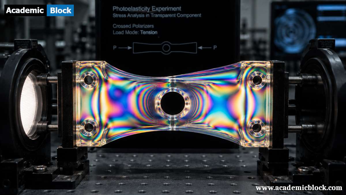
In a photoelastic experiment, polarized light is used to illuminate the stressed material. The polarized light passes through the material, and due to birefringence, it splits into two orthogonally polarized components. These components travel through the stressed material at different velocities, resulting in a phase difference.

Fringe Patterns

The phase difference between the two polarized components gives rise to interference patterns known as fringes. These fringes represent regions of equal stress and aid in visualizing the stress distribution within the material. By analyzing the fringe patterns, researchers can gain valuable insights into the magnitude and direction of the stresses present.

Types of Fringe Patterns

There are different types of fringe patterns, each offering insights into specific aspects of the stress field. The primary types of fringe patterns in photoelasticity include:

Isochromatic Fringes:

    • Characteristics: Isochromatic fringes are contour lines of equal color. Each fringe represents a specific difference in optical path length between the two orthogonal components of polarized light passing through the stressed material.
    • Information Provided: Isochromatic fringes indicate areas of equal stress difference. The color of the fringes corresponds to the order of the fringe, which is related to the stress difference in the material.

Isoclinic Fringes:

    • Characteristics: Isoclinic fringes are curves connecting points of equal principal stress direction. These fringes represent the orientation of the principal stress vectors within the material.
    • Information Provided: Isoclinic fringes provide information about the direction of the principal stresses at a given point. The spacing between isoclinic fringes is related to the shear stress on the plane.

Circular Fringes:

    • Characteristics: Circular fringes are concentric circles centered at points where the material is subjected to a point load or a circular symmetry of applied stresses.
    • Information Provided: Circular fringes indicate regions of constant shear stress. The number of fringes and their spacing can be related to the applied load or stress conditions.

Moiré Fringes:

    • Characteristics: Moiré fringes result from the interference between the fringe pattern and a grid or grating overlaid on the stressed material. The interference produces a new set of fringes with a different pattern.
    • Information Provided: Moiré fringes are used for quantitative analysis, providing a reference pattern that helps measure the deformation or strain in the material.

Compensator Fringes:

    • Characteristics: Compensator fringes are introduced by inserting a compensator, such as a quarter-wave plate, into the optical path. This alters the phase relationship between the two polarized components of light.
    • Information Provided: Compensator fringes are used to determine the direction of principal stresses by adjusting the compensator until the fringes become isochromatic. The orientation of the compensator then corresponds to the principal stress direction.

Fringes in Photoelastic Coatings:

    • Characteristics: In photoelastic coatings, fringes appear on the coating applied to the surface of a structure. These coatings are often used in experimental stress analysis of real-world components.
    • Information Provided: The fringes in photoelastic coatings reveal the stress distribution on the surface of the structure, providing information about stress concentrations and load transfer.

Digital Fringe Patterns:

    • Characteristics: With the advent of digital technology, fringe patterns can be captured using high-resolution cameras and analyzed digitally. Digital fringe patterns offer enhanced accuracy and the ability to store and share data more effectively.
    • Information Provided: Digital fringe patterns are used for advanced analysis techniques, including quantitative measurements and the application of image processing algorithms to extract detailed information about stress distribution.

Understanding these various types of fringe patterns is crucial for accurately interpreting photoelasticity experiments and extracting meaningful information about the stress field within a material or structure. Each type of fringe pattern provides unique insights into different aspects of the stress distribution, enabling researchers and engineers to make informed decisions about the design and performance of materials and components.

Mathematical equations behind the Photoelasticity

The mathematical equations behind photoelasticity involve the relationship between stress, birefringence, and the resulting fringe patterns. The following equations describe the key concepts in photoelasticity:

  1. Stress-Optical Law: The stress-optical law describes the relationship between the induced birefringence (Δn) in a material and the applied stress (σ). It is typically expressed as:Δn = C ⋅ σ ; Here, C is the stress-optical coefficient, a material property indicating the change in refractive index per unit stress.
  2. Birefringence and Phase Difference: The birefringence in a stressed material results in a phase difference (δ) between the two orthogonal components of polarized light passing through it. The relationship between birefringence and phase difference is given by:δ = (2π / λ)⋅Δn⋅d ; Where:
    • δ is the phase difference,
    • λ is the wavelength of light,
    • Δn is the induced birefringence,
    • d is the thickness of the material.
  3. Fringe Order: Fringe order (m) is a measure of the number of fringes observed in a photoelastic experiment. The relationship between fringe order, phase difference, and wavelength is given by:m = (δ / 2π) = (Δn ⋅ d) / λ ;
  4. Stress Analysis Equation: The stress at a particular point in a photoelastic material can be related to the fringe order by the following equation:σ = (m ⋅ λ) / C ⋅ d ; Where:
    • σ is the applied stress,
    • m is the fringe order,
    • λ is the wavelength of light,
    • C is the stress-optical coefficient,
    • d is the thickness of the material.

These equations form the basis for interpreting and quantifying stress in photoelastic experiments. Researchers and engineers use these equations in conjunction with the observed fringe patterns to analyze and understand the stress distribution within a material or structure.

Experimental Setup

Conducting a photoelastic experiment involves several key components, including a light source, a polarizer, a specimen, a polariscope, and an analyzer. The specimen is the material under investigation, and it is typically placed between the polarizer and the analyzer.

  1. Polarizer: This component polarizes the light before it enters the stressed material. It sets the initial polarization direction.
  2. Specimen: The material to be analyzed, subjected to mechanical stress. The stress-induced birefringence occurs within this material.
  3. Polariscope: A combination of optical elements that facilitates the observation of interference patterns produced by the stressed material.
  4. Analyzer: This component analyzes the light emerging from the specimen. By adjusting the analyzer, researchers can control the visibility of the interference fringes.

Applications of Photoelasticity

Photoelasticity finds applications in various fields due to its ability to provide detailed information about stress distribution in materials. Some notable applications include:

Structural Analysis

In civil and mechanical engineering, photoelasticity is employed to analyze and optimize the designs of structures such as bridges, buildings, and machine components. Engineers use photoelastic models to study stress concentrations and make informed decisions to enhance structural integrity.

Material Testing

Understanding how materials respond to stress is crucial for material scientists. Photoelasticity aids in studying the behavior of materials under different loading conditions, helping researchers design materials with enhanced mechanical properties.

Experimental Validation

Photoelasticity is often used to validate theoretical models and simulations. By comparing experimental results with theoretical predictions, researchers can verify the accuracy of their models and gain confidence in their understanding of material behavior.

Optics and Electronics

In optics, photoelastic materials are used to create devices such as modulators and switches. The stress-induced birefringence in these materials can be controlled to manipulate the polarization of light, enabling applications in telecommunications and imaging technologies.

Challenges and Limitations

While photoelasticity is a powerful tool, it is not without its challenges and limitations:

Model Scaling

Creating a photoelastic model that accurately represents a real-world structure requires careful consideration of scaling factors. The model must be scaled properly to ensure that the stress distribution accurately reflects the behavior of the full-scale structure.

Isotropic Materials

Photoelasticity is most effective in materials that exhibit stress-induced birefringence. Isotropic materials, which do not possess this property, are not suitable for photoelastic analysis.

Quantitative Analysis

Interpreting fringe patterns requires expertise, and extracting quantitative data from these patterns can be challenging. Advanced image processing techniques are often employed to enhance the accuracy of stress analysis.

Recent Advances in Photoelasticity

Recent advancements in technology and image processing have further expanded the capabilities of photoelasticity. Digital photoelasticity, for example, utilizes high-resolution cameras and computer algorithms to capture and analyze fringe patterns. This approach enhances the accuracy and efficiency of stress analysis.

Additionally, the integration of 3D printing technology has allowed for the rapid prototyping of complex photoelastic models. This enables researchers to create custom models with intricate geometries, providing a more realistic representation of real-world structures.

Final Words

Photoelasticity remains a vital and relevant technique in the field of material science and engineering. Its ability to visually represent stress distribution in a wide range of materials makes it an indispensable tool for structural analysis, material testing, and experimental validation. While facing challenges such as model scaling and quantitative analysis, recent advancements in technology have expanded the capabilities of photoelasticity, paving the way for future innovations. In this article by Academic Block, we have seen that, as researchers continue to push the boundaries of this technique, it will likely play a key role in advancing our understanding of material behavior and contributing to the development of safer and more efficient structures and materials. Please provide your comments below, it will help us in improving this article. Thanks for reading!

This Article will answer your questions like:

+ What is Photoelasticity and how does it visualize stress distribution in materials? >

Photoelasticity is a technique used to visualize stress distribution in materials by exploiting the optical properties of photoelastic materials. When mechanical stress is applied to these materials, it induces birefringence, where the material exhibits different refractive indices in different directions. By passing polarized light through a stressed photoelastic sample, stress-induced birefringence causes the light to split into differently polarized components, which can be captured and analyzed to visualize stress patterns and concentrations within the material.

+ How are photoelastic materials used to study stress patterns and structural integrity? >

Photoelastic materials are used in experimental setups to study stress patterns and assess structural integrity. These materials, typically transparent and exhibiting stress-induced birefringence, allow researchers to visualize how stress propagates through a component or structure. By analyzing the interference patterns formed when polarized light passes through a stressed photoelastic model, engineers can infer stress concentrations, identify potential failure points, and optimize designs to enhance durability and performance under real-world loading conditions.

+ What are the key principles behind photoelasticity and birefringence? >

Photoelasticity relies on the principles of birefringence exhibited by certain materials under stress. Birefringence is the property where light passing through a material splits into two polarized components with different refractive indices. When stress is applied to a photoelastic material, it alters the material's refractive index, resulting in phase differences between the polarized light components. These phase differences manifest as interference patterns (fringes) when viewed under a polariscope, providing a qualitative and quantitative visualization of stress distribution within the material.

+ How does photoelasticity differ from other stress measurement techniques like strain gauges? >

Photoelasticity differs from strain gauge techniques in several ways. While strain gauges directly measure strain (deformation) in materials by electrical resistance changes, photoelasticity visualizes stress patterns by analyzing light interference caused by stress-induced birefringence. Photoelasticity provides a qualitative view of stress distribution across the entire material surface, offering insights into stress concentrations and structural behavior under load, whereas strain gauges provide precise quantitative measurements at specific points. Additionally, photoelasticity is non-invasive and can be applied to transparent materials, whereas strain gauges require physical attachment to the material surface.

+ What types of materials and components are suitable for photoelastic analysis? >

Photoelastic analysis is suitable for a variety of transparent or semi-transparent materials that exhibit stress-induced birefringence, such as glass, polymers, and certain crystals. It is commonly applied to analyze stress in structural components like beams, shafts, and machine parts where understanding stress distribution and potential failure points is critical for design optimization and durability assessment.

+ How is stress concentration and fracture analysis performed using photoelastic models? >

Stress concentration and fracture analysis using photoelastic models involve applying controlled loads to the model and observing the resulting stress patterns through a polariscope. Areas of high stress concentration are visualized as dense fringe patterns, indicating potential failure points where fractures are likely to initiate under operational conditions. By analyzing these fringe patterns and their distribution, engineers can optimize component designs to mitigate stress concentrations and enhance structural integrity.

+ What role does polarized light and optical retardation play in photoelastic experiments? >

Polarized light is fundamental in photoelastic experiments as it reveals stress-induced birefringence in materials. When polarized light passes through a stressed photoelastic sample, stress alters the material's refractive index, causing different polarization states and phase shifts between light components. Optical retardation, quantified by the phase difference between these components, correlates with the magnitude of stress within the material. This optical phenomenon is critical for interpreting stress states and analyzing stress distribution patterns using fringe analysis techniques.

+ How are isochromatic and isoclinic fringes used to interpret stress states? >

Isochromatic and isoclinic fringes are key tools in interpreting stress states in photoelasticity. Isochromatic fringes represent lines of constant difference in principal stresses, providing a quantitative view of stress magnitude across the material. Isoclinic fringes, on the other hand, depict the orientation of principal stress directions through patterns of constant retardation angles. Together, these fringes allow engineers and researchers to analyze stress distribution, determine stress concentrations, and assess the structural integrity of materials under various loading conditions.

+ What are the advantages of using photoelasticity for engineering and design applications? >

Photoelasticity offers several advantages for engineering and design applications. It provides a visual and qualitative assessment of stress distribution in complex geometries and transparent materials, aiding in optimizing structural designs to minimize stress concentrations and potential failure points. Photoelastic models are non-destructive and allow for real-time observation of stress patterns under varying loads, facilitating iterative design improvements and validation of theoretical stress analysis. Moreover, photoelasticity can reveal insights into material behavior that complement and validate numerical simulations, enhancing confidence in engineering solutions.

+ How does dynamic photoelasticity contribute to studying transient stress effects? >

Dynamic photoelasticity studies transient stress effects by observing how stress propagates and redistributes in materials under dynamic loading conditions. By applying rapid mechanical or thermal changes to a photoelastic model and analyzing the resulting fringe patterns in real-time, researchers can study stress wave propagation, impact dynamics, and vibration-induced stresses. This real-time visualization of transient stress effects provides valuable insights into material response and helps engineers optimize designs for dynamic performance and durability in applications such as automotive crash testing, aerospace structures, and machinery subjected to impact or oscillatory loads.

+ What are the limitations and factors affecting accuracy in photoelastic analysis? >

Photoelastic analysis has limitations primarily related to the assumptions of linear elasticity and the availability of suitable photoelastic materials. Accuracy can be affected by factors such as material homogeneity, stress concentration near boundaries, and environmental conditions affecting optical clarity. Calibration and interpretation of fringe patterns require expertise to avoid misinterpretation of stress states. Additionally, dynamic effects and non-linear material behavior may require advanced modeling and validation techniques to correlate photoelastic observations with actual stress distributions accurately.

+ How are photoelastic images processed and analyzed to extract stress information? >

Photoelastic images are processed and analyzed using fringe interpretation techniques to extract stress information. This involves identifying and measuring isochromatic and isoclinic fringes using polariscope images. Digital image processing tools may be employed to enhance fringe visibility and quantify stress magnitudes based on optical retardation data. Calibration against known stress conditions and geometric models helps validate the analysis. Advanced algorithms and software aid in automated fringe detection and stress mapping, providing engineers with detailed insights into stress distribution and structural performance for optimizing designs and ensuring reliability in engineering applications.

Hardware and software required for Photoelasticity

Performing photoelastic experiments requires specific hardware and software tools to capture, analyze, and interpret the fringe patterns generated by stressed materials. Below is a list of essential hardware and software components for photoelasticity:

Hardware:

  1. Light Source: A stable and controllable light source, often a white light source or a monochromatic light source with a known wavelength.
  2. Polarizer: A device that polarizes the light before it enters the stressed material. This is usually placed between the light source and the specimen.
  3. Specimen: The material under investigation, typically made of a photoelastic material transparent to the selected wavelength of light.
  4. Polariscope: An optical setup comprising two polarizers and a set of optical elements to observe and analyze the interference patterns produced by the stressed material. It includes a polarizer, a specimen, and an analyzer.
  5. Analyzer: An optical component that can be rotated to control the visibility of the interference fringes. It is placed after the specimen in the optical path.
  6. Compensator: Optional, but often used to enhance the visibility and interpretation of fringes. A compensator introduces a controlled phase difference and helps in determining the principal stress directions.
  7. Camera: A high-resolution camera to capture images of the observed fringe patterns. Modern experiments may use digital cameras for enhanced image quality.
  8. Mounting and Loading System: A system to securely mount and load the specimen to apply controlled and known loads. This can include mechanical loading devices or fixtures.
  9. Fringe Viewing System: Optical elements or a camera system to view and capture fringe patterns accurately.
  10. Optional Accessories: Various accessories such as filters, lenses, and adapters to optimize the experimental setup.

Software:

  1. Image Capture Software: Software to control and capture images from the camera. This can be the manufacturer’s proprietary software or third-party applications.
  2. Image Processing Software: Specialized software for processing digital images of fringe patterns. This includes removing noise, enhancing contrast, and extracting quantitative data. Examples include MATLAB, ImageJ, or specialized software provided by manufacturers.
  3. Fringe Analysis Software: Software designed specifically for analyzing fringe patterns and extracting quantitative data. It may include algorithms for fringe counting, phase shifting, and contour mapping. Some polariscope systems come with built-in fringe analysis capabilities.
  4. Data Visualization and Presentation Software: Software for visualizing and presenting the analyzed data. This could include tools like Microsoft Excel, MATLAB, or other plotting software.

Key figures in the field of Photoelasticity

While, Sir David Brewster made significant contributions to the understanding of birefringence, a phenomenon central to photoelasticity, the development of photoelasticity as a distinct experimental technique is more closely associated with the work of Sir Francis Arthur Bain.

Sir Francis Arthur Bain, a British scientist, is considered a pioneer in the field of photoelasticity. In the early 20th century, Bain introduced the polariscope, a crucial instrument for conducting photoelastic experiments. The polariscope, which he developed in the 1900s, allowed researchers to visualize and analyze stress distribution in materials by observing the interference patterns or fringes produced when polarized light passes through stressed transparent or translucent materials.

Bain’s contributions laid the groundwork for the development and widespread application of photoelasticity in various scientific and engineering disciplines. While Brewster’s earlier work on birefringence contributed to the theoretical understanding of the phenomenon, it was Bain’s practical innovations that transformed photoelasticity into a valuable experimental technique for studying stress and strain in materials.

Future Prospects and Emerging Trends

As technology continues to advance, the field of photoelasticity is likely to witness further innovations. The integration of artificial intelligence and machine learning algorithms may streamline the analysis of fringe patterns, making stress analysis more accessible to a broader range of researchers and engineers.

Furthermore, the development of new photoelastic materials with enhanced sensitivity and durability will contribute to the continued growth of this field. These materials may exhibit improved stress-optical coefficients and better resistance to environmental factors, expanding the range of applications for photoelasticity.

Facts on Photoelasticity

Discovery by Sir David Brewster: Photoelasticity traces its roots back to the discovery of birefringence by Sir David Brewster in the 19th century. He observed that certain transparent materials exhibited double refraction under stress.

Polariscope Development by Sir Francis Arthur Bain: The development of photoelasticity as a technique is closely associated with Sir Francis Arthur Bain, who introduced the polariscope in the early 20th century. The polariscope became a key instrument for conducting photoelastic experiments.

Stress-Optical Coefficients: Different materials exhibit varying degrees of stress-induced birefringence. The relationship between stress and birefringence is characterized by stress-optical coefficients, denoted by the symbol CC.

Isochromatic Fringes: Isochromatic fringes in photoelasticity are contour lines of equal color. They represent regions of the material with equal stress differences.

Isoclinic Fringes: Isoclinic fringes are curves connecting points of equal principal stress direction. They provide information about the orientation of principal stresses within the material.

Circular Fringes: Circular fringes in photoelasticity are concentric circles centered at points where the material is subjected to a point load or circular symmetry of applied stresses. They indicate regions of constant shear stress.

Moiré Fringes: Moiré fringes result from the interference between the fringe pattern and a grid or grating overlaid on the stressed material. Moiré patterns are useful for quantitative analysis.

Compensator Fringes: Compensator fringes are introduced using devices like quarter-wave plates to aid in determining the principal stress directions.

Digital Photoelasticity: With advancements in technology, digital photoelasticity has become prevalent. High-resolution cameras and sophisticated image processing techniques are employed for more accurate and efficient fringe pattern analysis.

Applications in Structural Analysis: Photoelasticity finds widespread applications in civil and mechanical engineering for analyzing stress distribution in structures like bridges, buildings, and machine components.

Material Testing: Photoelasticity is utilized in material science to study the response of materials to different loading conditions. It aids in designing materials with enhanced mechanical properties.

Experimental Validation: Photoelasticity is often used to validate theoretical models and simulations, providing experimental confirmation of stress distribution patterns.

Optics and Electronics Applications: In optics, photoelastic materials are used to create devices like modulators and switches. The stress-induced birefringence can be controlled for applications in telecommunications and imaging technologies.

Challenges: Challenges in photoelasticity include model scaling to represent real-world structures accurately, the suitability of materials (isotropic vs. anisotropic), and the need for expertise in interpreting fringe patterns.

Future Prospects: The integration of AI, machine learning, and the development of new photoelastic materials with enhanced properties are expected to shape the future of photoelasticity, making it more accessible and applicable in various fields.

Academic References on Photoelasticity

  1. Frocht, M. M. (1941). Photoelasticity: Volume I – The Generalized Theory of Photoelasticity. John Wiley & Sons.
  2. Malusa, M. F. (1964). Photoelasticity for Designers. Prentice-Hall.
  3. Zemanek, J. (1983). Photoelasticity: Principles and Methods. Springer.
  4. Jones, R. M. (1989). Mechanics of Composite Materials. Taylor & Francis.
  5. Kobayashi, A. S. (2005). Introduction to Photoelasticity. Courier Dover Publications.
  6. Holister, G. S. (2010). Introduction to Experimental Stress Analysis. Prentice-Hall.
  7. Malvern, L. E. (1969). Introduction to the Mechanics of a Continuous Medium. Prentice-Hall.
  8. Gooch, G. A., & Rowe, J. P. (1990). Photoelastic and Electro-Optic Properties of Crystals. John Wiley & Sons.
  9. Sutton, M. A., Wolters, W. J., Peters, W. H., Ranson, W. F., & McNeill, S. R. (1983). Determination of displacements using an improved digital correlation method. Image and Vision Computing, 1(3), 133-139.
  10. Post, D., & Dooley, D. (1977). Applications of photoelastic coatings to composites. Experimental Mechanics, 17(6), 215-220.
  11. Ramesh, K., & Krishnamurthy, C. V. (1997). Digital Photoelasticity: Advanced Techniques and Applications. Springer.
  12. Shukls, A., & Dally, J. W. (2017). Experimental Solid Mechanics. College House Enterprises.
  13. Frocht, M. M. (1956). Photoelasticity: Volume II – Photomechanics. John Wiley & Sons.
0 0 votes
Article Rating
Subscribe
Notify of
guest
0 Comments
Oldest
Newest Most Voted
Inline Feedbacks
View all comments
0
Would love your thoughts, please comment.x
()
x